
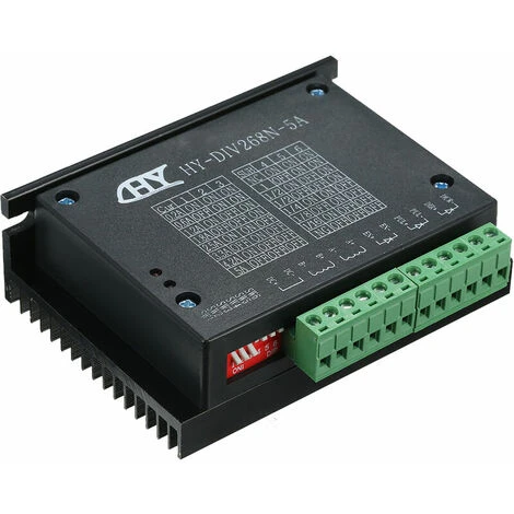


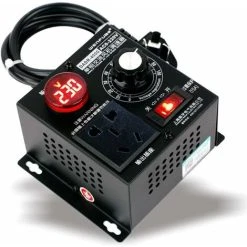
HEGUYEY Hy-Div268N-5A Dual Phase Hybrid Subdivision-Type Dc Drive Power Supply 12 48V Power Supply
£24.93
- High quality products, low prices.
- Free 1 year warranty period
- SSL encryption, absolutely safe shopping
- Free Shipping, No Compromise on Quality

- ManoMano ReferenceME71269093
- Warranty2 years
- Product codeM1-X002-20230316-11040-CJ
Features:
Average current control, two-phase sinusoidal current output.
DC 12 ~ 48V power supply, internal integration of 12V and 5V regulator.
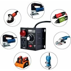
Optically isolated signal input/output. Over voltage, under voltage, over current and white short circuit protection. Widely used in engraving machine, CNC machine tools, machine tools. packaging and other high resolution requirements on the device.
Specification:
Input Voltage: DC 12~48V Input
Input Current: 1-5 Amps, select the motor of a stepper motor.
Output Current: 0.2A~5A
Temperature Working Temperature: -10 to 45 ℃
Temper Storage ature: -40℃ to 70℃
Material: ABS and Metal
Item Size: 10.4 * 8.6 * 3.3cm / 4.09 * 3.39 * 1.3in (L * W * H)
Item Weight: Approx. 218g / 7.69oz
Package size: 11.9 * 9 * 3.9cm / 4.69 * 3.54 * 1.54in (L * W * H)! Package Weight: 243g / 8.57oz
Package List: 1 * Stepper Motor Drive
Instruction: Control signal interface
– Figure 1 is a wiring diagram of the drive
– 1, the definition of control signals
PUL +: step pulse signal is the input side or the positive pulse signal input positive terminal
PUL-: negative input pulse signal negative input or a positive pulse signal DIR +: stepping direction signal input to the positive terminal or signal input negative pulse to positive terminal
DIR -: Negative or reverse pulse signal input negative terminal stepping direction signal input
EN +: offline can reset the signal input side is
FR-: offline can reset negative terminal d' 39;signal input
Offline enable signal is active, reset drive failure to prohibit pulse, drive output
Power component is disabled , the motor holding torque.
– Control signal connections
– PC control signal can be high, also can be low effective. When active high, the control signal
– Negative side together as a signal to active low, positive side of all control signals together as a common signal.
– Par For example, the open-collector and PNP output interface circuit diagram is as follows:
Figure 2. Output interface circuit. input (common cathode connection) – Note: VCC is 5V, short R; – VCC value of 12V, R 1K, more than 1/8W resistance;
– VCC value of 24V, R 2K, more than 1/8W resistance;
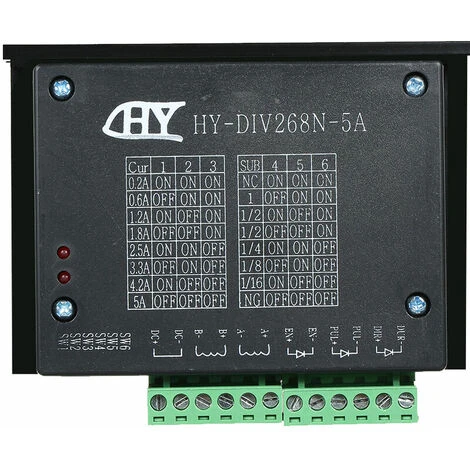
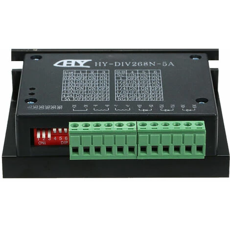
Function selection ( DIP switch on the control panel)
– Set the motor per revolution step
The dimmer to set the number of steps per motor revolution is 200 (full step), 400 (2 segments), 1600 (8 segments), 3200 steps (16 segments).
User can drive the front panel DIP switch SW3 is SW4 bit of the drive to set the number of steps (such as Table 1) :
Table 1
– Set the output phase current
– Drive the torque stepper motor, SW1, SW2 is used to set the intensity of the output phase of the dimmer (RMS), the position of the switch
– Corresponding to the output current, the value of the output current corresponding to the different types of dimmers. shown in table 2.
– Output current (A
Table 2
Current setting
– Half-flow functionality
– The semi-flux function is a 200ms step pulse, the driver output current is automatically reduced to the rated output current50%, used to prevent motor heating Fourth, the power supply interface
– 1, DC+, DC-: to connect motor power supply
– DC+: DC power level, power Supply voltage is 12-48 V. The maximum current is 5 A. The power supply current level
DC-: DC is negative.
2, A + AB + B-: to connect the stepper motor to Two-phase hybrid stepper or
Two-phase hybrid stepper motor drive and motor with the four-wire system, parallel and series motor windings, and connection method, high-speed performance, but the current d&# 39; attack is important (for current d motor winding 1.73 times), connected in series when the drive current is equal to the motor winding current. installation
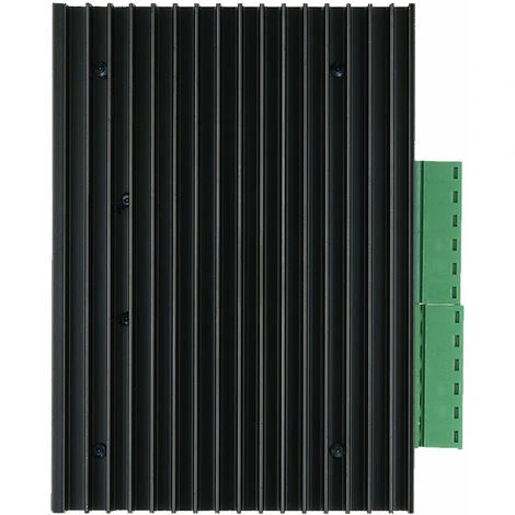
– Around have 20mm space, can not be placed next to the other heating equipment, to avoid dust, mist oil, corrosive gases, high humidity is too high and strong vibration. +
Figure 3.
Six fault diagnosis
1, the status light shows
RUN: green light in the normal work.
ERR: red light, power, light, power indicator
Six fault diagnosis
1, the status light indicates
RUN: green light in the normal work.
ERR: red light, power , light, power indicator
Be the first to review “HEGUYEY Hy-Div268N-5A Dual Phase Hybrid Subdivision-Type Dc Drive Power Supply 12 48V Power Supply”
Related products
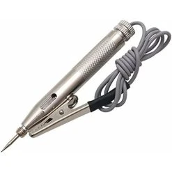


Voltage testers
MIMIY Briggs Stratton 690115 Walbro LMT 5-4993 Carburetor 12.5 HP Lawn Machine 690115
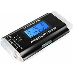
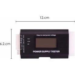
Voltage testers
Reviews
There are no reviews yet.